1Learning Outcomes
Use load and store assembly instructions and compute memory addresses as base register plus immediate offset.
Sign-extend signed partial loads with
lbandlh.Explain why partial stores do not need to sign- or zero-extend.
🎥 Lecture Video
5:00 onwards
2RISC-V Data Transfer Basics
Consider the memory access syntax for loading and storing words shown in Table 1:
Table 1:RV32I Instructions: Load word (lw), Store word (sw).
2.1Load Word
The load word instruction:
Computes a memory address
R[rs1]+immLoad a word from this address in memory,
M[R[rs1] + imm][31:0]......into a destination register,
rd.
The memory address is computed with register and immediate arithmetic. rs1 is called the base register. The immediate imm is called the offset and is a numeric constant that must be known at assembly time.
Let’s look at an example:
lw x10 12(x5)In Figure 1, executing this lw instruction loads the word 0x00564253 from memory (at address 0x10C) into register x10.
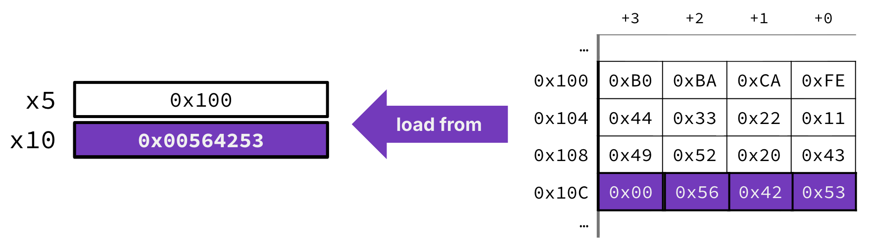
Figure 1:Illustration of lw x10 12(x5).
Show Explanation
lw x10 12(x5) fields:
Operation: Load word (4 bytes on RV32I)
Base register:
x5, where the value at this register isR[x5]or0x100.Offset: the immediate
12Destination register:
x10.
Read an earlier section for how to read the little endian memory layout.
Compute address:
0x100 + 12is0x10C.Read the word at address
0x10C. Starting from this address, the bytes are0x53,0x42,0x56, and0x00.If we assume the memory layout is showing a little endian architecture, we construct the 32-bit value
0x00564253. Setx10to this 32-bit word.
2.2Store Word
The store word instruction:
Computes a memory address
R[rs1]+immfrom the base registerrs1and the offsetimm.Store the word in the source register
rs2......to the word in memory,
M[R[rs1] + imm][31:0].
Let’s look at an example:
sw x10 0(x5)In Figure 2, executing this sw instruction stores the word 0x12345678 in register x10 to memory (at address 0x100).
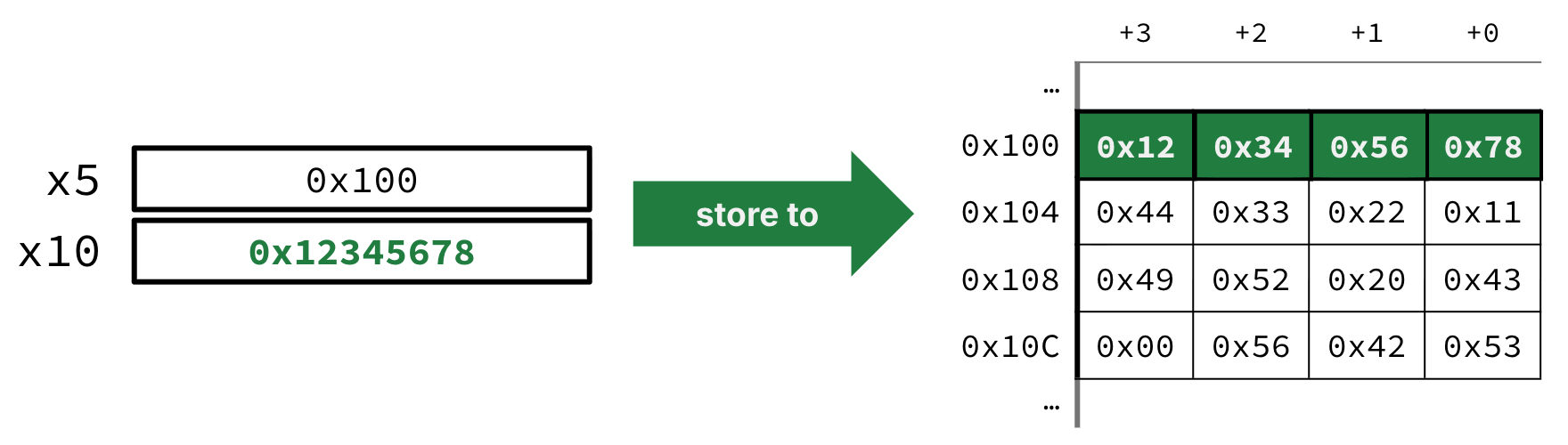
Figure 2:Illustration of sw x10 0(x5).
Show Explanation
sw x10 0(x5) fields:
Operation: Store word (4 bytes on RV32I)
Base register:
x5, where the value at this register isR[x5]or0x100.Source register:
x10.Offset: the immediate
0
Read an earlier section for how to read the little endian memory layout.
Compute address:
0x100 + 0is0x100.The word in register
x10is0x12345678.Store this word at address
0x100. Starting from this address, the bytes should be0x78,0x56,0x34, and0x12(again, assuming a little endian architecture).
2.3Endianness and Alignment
This section is a good time to step back and realize that we have now learned enough to interpret the actual RISC-V specification!
From the RV32I Specification:
In RISC-V, endianness is byte-address invariant.
In a system for which endianness is byte-address invariant, the following property holds: if a byte is stored to memory at some address in some endianness, then a byte-sized load from that address in any endianness returns the stored value.
RISC-V therefore supports both little-endian and big-endian architectures, and loads and stores are consistent with the endianness of the architecture. As an example:
In a little-endian configuration, multibyte stores write the least-significant register byte at the lowest memory byte address, followed by the other register bytes in ascending order of their significance. Loads similarly transfer the contents of the lesser memory byte addresses to the less-significant register bytes.
From the RV32I Specification:
Regardless of EEI[2], loads and stores whose effective addresses are naturally aligned shall not raise an address-misaligned exception. Loads and stores whose effective address is not naturally aligned to the referenced datatype (i.e., the effective address is not divisible by the size of the access in bytes) have behavior dependent on the EEI. ... Misaligned accesses are occasionally required when porting legacy code...
According to the RISC-V standard, loads and stores of words should specify word-aligned addresses. For RV32I, this means R[rs1] + imm should be a multiple of 4. Addresses that are not word-aligned produce behavior that is implementation-dependent. Put another way, while RISC-V technically allows misaligned accesses to support legacy code, it is very slow and messy. You should treat the “should” as a “must” to avoid “scribbling” all over the memory. :-)
3Partial Loads and Stores
We often work with data types smaller than 32 bits, like 8-bit characters[3]. It would be wasteful to use a full word for these, so RISC-V supports instructions for bytewise data transfers.
Recall that registers are themselves are word-sized. The RV32I specification therefore defines what to do with the other bytes when loading or storing byte-sized or half-word-sized data.
3.1Store
Table 2:RV32I store instructions.
| Instruction | Name | Description |
|---|---|---|
sb rs2 imm(rs1) | Store Byte | M[R[rs1] + imm][7:0] = R[rs2][7:0] |
sh rs2 imm(rs1) | Store Half-word | M[R[rs1] + imm][15:0] = R[rs2][15:0] |
sw rs2 imm(rs1) | Store Word | M[R[rs1] + imm][31:0] = R[rs2][31:0] |
Table 2 demonstrates the RV32I Specification:
The SW, SH, and SB instructions store 32-bit, 16-bit, and 8-bit values from the low bits of register rs2 to memory.
Consider the instruction:
sb x10 0(x5)As shown in Figure 3, this store byte instruction then ignores the upper bytes in the source register x10 and only considers the least significant byte R[x10][7:0] (the value 0xEF). This single byte is then stored to memory at address 0x100.
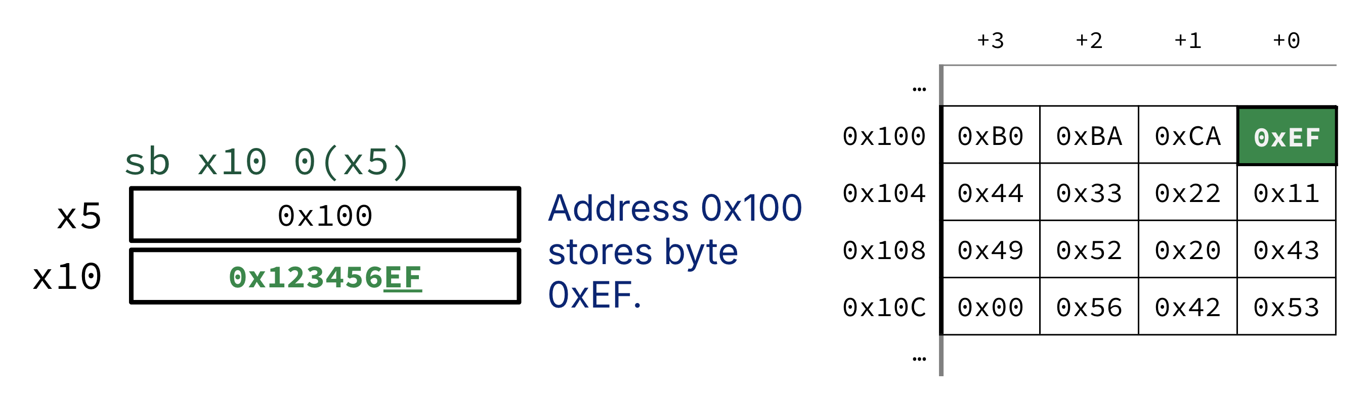
Figure 3:Example store byte instruction in memory.
3.2Load
The Load Byte instruction lb plucks a single byte from memory and (analogous to sb) places the byte in R[rd][7:0], the lowest byte position of the destination register rd. However, unlike stores, loads of sub-word widths must consider what to put in the upper bits, or R[rd][31:8] (see x10 in Figure 4).
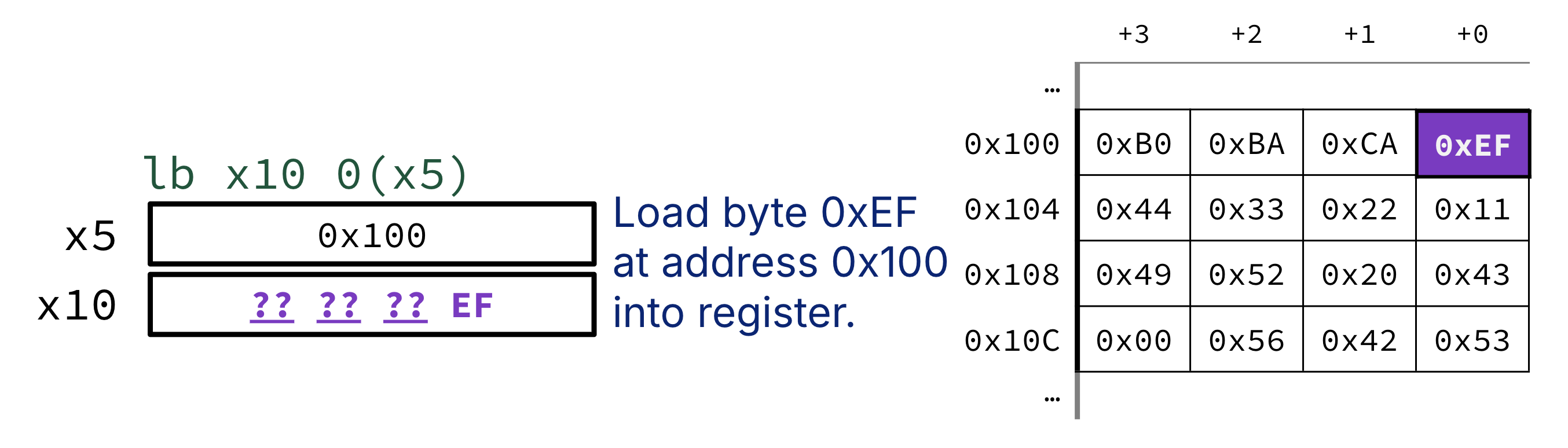
Figure 4:Example load byte instruction in memory. lb x10 0(x5) loads in 0xEF but also must determine how to fill the upper 24 bits of x10.
Because assembly operations determine how to interpret operands, we therefore define two “load byte” operations: Load Byte lb and Load Byte Unsigned lbu.
lb: If the target value should be a signed two’s complement number, sign extend. The most significant bit of the byte loaded from memory determines if the number is negative. In Figure 4,0xEF(0b11101111) has sign bit1yields a resultR[x10]of0xFFFFFEF. If the byte loaded in were, say,0x73(0b01110011), we fill in upper bits with0to yield a resultR[x10]of0x00000073.[4]lbu: If the target value should be an unsigned number, simply zero-extend. If the instruction in Figure 4 were insteadlbu x10 0(0x5), then the resultR[x10]would be0x000000EF, regardless of the bits of0xEF.
Table 3:RV32I load instructions.
| Instruction | Name | Description |
|---|---|---|
lb rd imm(rs1) | Load Byte | R[rd] = M[R[rs1] + imm][7:0] (Sign-extend) |
lbu rd imm(rs1) | Load Byte (Unsigned) | R[rd] = M[R[rs1] + imm][7:0] (Zero-extend) |
lh rd imm(rs1) | Load Half-word | R[rd] = M[R[rs1] + imm][15:0] (Sign-extend) |
lhu rd imm(rs1) | Load Half-word (Unsigned) | R[rd] = M[R[rs1] + imm][15:0] (Zero-extend) |
lw rd imm(rs1) | Load Word | R[rd] = M[R[rs1] + imm][31:0] |
The execution environment interface (EEI). We do not discuss the EEI in this course.
Additionally, RGB colors are 24-bit values; each of the three color channels is 8-bit wide.
In the lecture video, Professor Nikolic makes the analogy that sign extension is like putting a dollop of avocado on one side of toast, then smearing the top bit all over the upper bits.