1Learning Outcomes
Use the stack pointer to push large amounts of data onto the stack.
Translate array accesses in C code into assembly instructions.
Identify one register convention by name: the stack pointer
spis registerx2.
No video. We recommend pulling up the memory section of the RISC-V Green Card.
2Local variables on the stack
So far, we have been able to translate very tiny amounts of C code to fit into registers. If we have too many (data) words to fit into registers, we must use memory.
3Register Conventions and Register Names
As mentioned earlier, a register can also be referred to by its register name. Register names define convention—that is, specifying how assembly instructions should use specific registers for specific common functions. These restrictions help build “agreement” upon how to translate separate components of a program so that the assembly instructions slot together.
The RISC-V green card lists all register names; we begin introducing and using them in this example.
4Problem Description
Translate the below C program by only using the temporary registers t0, t1, t2, and the stack pointer sp . You may access memory as needed.
1 2 3 4 5 6int a = 5; char b[] = "string"; // Array will get stored on stack int c[10]; uint8_t d = b[3]; c[4] = a+d; c[a] = 20;
5Setup
We will use temporary registers to store addresses, arithmetic data, and so on. We will store local variable on the stack by assigning each variable to some offset from our stack pointer sp.
The exact addresses of these local variables don’t matter, so long as we’re consistent. Suppose we use the following assignment:
| Variable | Address relative to stack pointer |
|---|---|
int a | 0(sp) |
char b[7] | 4(sp) |
int c[10] | 12(sp) |
uint8_t d | 52(sp) |
6Solution
Here is the full assembly translation of the original C code:
1 2 3 4 5 6 7 8 9 10 11 12 13 14 15 16 17 18li t0 5 # R[t0] = 5 sw t0 0(sp) # store int a on stack li t0 0x69727473 # load "stri" sw t0 4(sp) # store first part of string li t1 0x0000676E # load rest of string sw t1 8(sp) # store rest of string lb t0 7(sp) # 4(sp) from b, 3(sp) from [3] sb t0 52(sp) # store into d lw t0 0(sp) # load a lbu t1 52(sp) # load d add t2 t0 t1 # R[t2] = a+d sw t2 28(sp) # 12(sp) from c, 16(sp) from [4] li t0 20 # R[t0] = 20 lw t1 0(sp) # R[t1] = a slli t1 t1 2 # 5*sizeof(int) = 5*4 = 5<<2 addi t1 t1 12 # t1 from [a], 12 from c add t1 t1 sp # compute &c[a] sw t0 0(t1) # c[a] = 20
We discuss line-by-line translation below. For each section, try to use the image to interpret why we specified the corresponding assembly instructions. Then, check your reasoning.
6.1Line 2: int a = 5;
1 2li t0 5 # R[t0] = 5 sw t0 0(sp) # store int a on stack
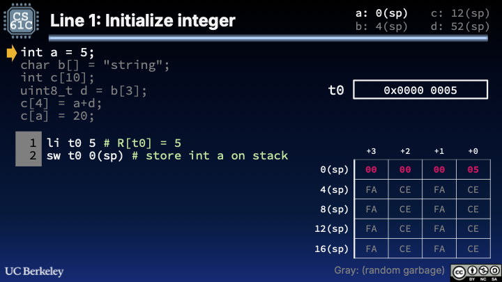
Figure 1:Line 1 of Stack Pointer Example.
Show Explanation
To initialize int a = 5, store a 4B word onto the stack. Because sw requires our word data to be in a register first, execute li (load immediate) and then sw.
6.2Line 3: Initialize string char b[] = "string";
We would like to store the bytes of "string" onto our stack, starting at location 4(sp). There is a straightforward but tedious way to do so, and a concise way that requires a bit of cleverness.
One approach (straightforward but tedious):
1 2 3 4 5 6 7 8 9 10 11 12 13li t0 0x73 sb t0 4(sp) li t0 0x74 sb t0 5(sp) li t0 0x72 sb t0 6(sp) li t0 0x69 sb t0 7(sp) li t0 0x6E sb t0 8(sp) li t0 0x67 sb t0 9(sp) sb x0 10(sp)
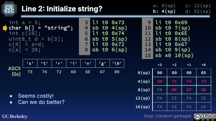
Figure 2:Line 2 of Stack Pointer Example.
Show Explanation
The char bytes of "string" are {0x73, 0x74, 0x72, 0x69, 0x6E, 0x67, 0x00} as per ASCII. Use li and sb repeatedly to store these bytes at addresses 4(sp), 5(sp), etc. Detail: We don’t li for the null terminator and instead directly store x0, the hardwired 0, for the null terminator '\0' (which has ASCII value 0x00).
Alternate approach with much fewer instructions:
1 2 3 4li t0 0x69727473 # load "stri" sw t0 4(sp) # store first part of string li t1 0x0000676E # load rest of string sw t1 8(sp) # store rest of string
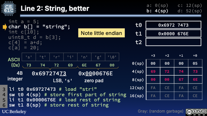
Figure 3:Line 2 of Stack Pointer Example, concise version.
Show Explanation
We could cut the 13 load immediate/store byte instructions into 4 instructions: load immediate, store word.
This requires us to think about characters not as individual bytes, but rather groups of 4 characters. Remember, characters are stored as bits, and those bits can also represent integers. As long as we store the right 32-bit value into data, then those 32 bits can be interpreted as characters when we need it.
Second, note that words are stored as little endian. But character arrays should be stored in increasing address order. If we are representing every group of 4 characters as a 4B word, we will need to reverse the bytes such that the first character is stored at the earliest address, and the fourth character at the highest address. If we don’t do this, our character string will not be stored properly in order.
First 4B word:
{'s', 't', 'r', 'i'}is{0x73, 0x74, 0x72, 0x69}. On this little endian architecture, we should store the 32-bit immediate0x69727473. Little endian means least significant byte is stored at the lowest address.0x73('s') is stored at4(sp),0x74('t') at5(sp), etc.Second 4B word:
{'n', 'g', '\0'}is{0x6E, 0x67, 0x00}, i.e. just three bytes. But we need to make a 4-byte immediate, so a reasonable choice would be to sub in zero as the fourth byte. On this little endian architecture, we should store the 32-bit0x0000676E(where the “zero pad” is from my choice to insert a zero byte after the null terminator). Little endian means least significant byte is stored at the lowest address, sosw t1 8(sp)indicates0x6E('n') is stored at8(sp),0x67('g') at9(sp),0x00('\0') at10(sp), and our dummy extra byte at11(sp).
Two detailed questions raised in class a while ago:
Why use
t0andt1? Why not justt0? Yes, I could’ve done this (the original solution also minimized registers used). But I wanted to draw the two immediates stored to separate registers on the slide.liis a pseudoinstruction that generally resolves toaddi. Doesn’taddionly allow for 12b immediates, not the 32b immediates specified? Yes, you’re totally right.lias a pseudoinstruction sometimes resolves to a pair of instructions,lui/addi, where the former is “load upper immediate.”luilets us load the upper 20 bits, and addi lets us load the lower 12 bits. More later; it turns out there is a complex signed addition note to consider :-)
6.3Line 4: Uninitialized array int c[10];
No instructions needed.
!["Uninitialized int c[10]: slide notes no instructions run; stack shows int a and string data unchanged while 12(sp) onward remains labeled random garbage for c’s reserved space."](/build/sp-example-3-dcacddda0e2a5a9cf41453cfb5d0d69f.png)
Figure 4:Line 3 of Stack Pointer Example.
Show Explanation
We’re not actually storing any data into memory, so no instructions need to be executed. At this time it’s good to remember that our Setup was a design decision (that we, as the human compiler, made) that doesn’t actually resolve to any instructions, either.
6.4Line 4: Read array element uint8_t d = b[3];
1 2lb t0 7(sp) # 4(sp) from b, 3(sp) from [3] sb t0 52(sp) # store into d
!["uint8_t d = b[3]: lb from 7(sp) loads byte 0x69 into t0, then sb writes that byte to 52(sp); memory highlights the indexed character and d’s low byte."](/build/sp-example-4-ba9f42e3255c5cbfe514f92e8c71a923.png)
Figure 5:Line 4 of Stack Pointer Example.
Show Explanation
This step practices how to do array indexing, thereby revealing the true reason why lb and sw use the base register + offset convention for addresses. Load b[3] (located at (3 + (4 + R[sp]))) and store byte to the location of d (located at 52 + R[sp]).
6.5Line 5: Store array element c[4] = a + d;
1 2 3 4lw t0 0(sp) # load a lbu t1 52(sp) # load d add t2 t0 t1 # R[t2] = a+d sw t2 28(sp) # 12(sp) from c, 16(sp) from [4]
!["c[4] = a + d example: lw and lbu bring int a and uint8_t d into t0 and t1, add puts the sum in t2, and sw stores it at 28(sp); a diagram lists word offsets 12 through 32 for c[0] through c[5]."](/build/sp-example-5-4265c45e5728ccdc8db980d87c29d842.png)
Figure 6:Line 5 of Stack Pointer Example.
Show Explanation
This step practices (1) more array indexing, and (2) how to add together two variables that were originally stored in memory.
In order to add two variables stored in memory, we need to load both variables from memory into registers (L9-10), then add them (L11).
The last line computes
&c[4]. Sincecstarts at12(sp), andsizeof(int)is4,c[4]is located 16 bytes from the start ofc, or (12 + 16) = 28 bytes fromsp.
6.6Line 6: Variable array indexing c[a] = 20;
This line is the most challenging of the bunch, so we recommend working it out via Venus once you learn how to use Venus in lab.
1 2 3 4 5 6li t0 20 # R[t0] = 20 lw t1 0(sp) # R[t1] = a slli t1 t1 2 # 5*sizeof(int) = 5*4 = 5<<2 addi t1 t1 12 # t1 from [a], 12 from c add t1 t1 sp # compute &c[a] sw t0 0(t1) # c[a] = 20
Show Explanation
This step is different from the previous one because we must compute the array address using another variable, a. So we can’t just compute relative addressing. Instead, we must compute the absolute address in registers first, then store at that address.
Line 1. Register
t0contains the data we’d like to store,20.Lines 2-5. Compute our address
&c[a], which in bytes is4*a + &c(becausesizeof(int)is4), which relative to the stack pointer is4*a + 12 + sp.Line 2. Load in
atot1.Line 3. Multiply
aby4. This is equivalent to bitshifting left by 2. We haven’t coveredslliexplicitly in lecture, but looking this up in our refcard we see thatslliis shift left logical immediate.`0x5 = 0b101 # a 0b10100 # a << 2 = 20 = 0x14 # a << 2 in decimal, hexLine 4. Add
12. This is the offset ofcwith respect tosp.20 + 12 = 32 # in decimal = 0x20 # in hexLine 5. Add sp. This completes the address.
Line 6: Store the desired data (register
t0) at the desired address (registert1, with zero offset, because we’ve computed the absolute address already).
7Quick Checks
Show Answer
E. &c[a]. The value in register t1 is defined (with Verilog syntax) as R[t1]; at this point, it is (R[t1] * 4) + 12 + R[sp]. The register value R[t1] is used as an address–it is the memory location to which we store the word R[t0].
Show Answer
a is a variable. Its value happens to be 5 at runtime, but compilers can’t necessarily simulate program runtime!