1Learning Outcomes
Given instruction sequences and a processor architecture, identify potential control hazards.
Explain why a write-then-read register file reduces pipeline stalls due to potential data hazards.
Explain how forwarding (i.e., bypassing) reduces pipeline stalls due to potential data hazards.
Implement two forwarding paths, one from
MEMtoEXand one fromWBtoEX, in the five-stage pipelined processor.Explain why data hazards involving load instructions in a given instruction sequence can incur an inevitable pipeline stall.
🎥 Lecture Video: Data Hazards
🎥 Lecture Video: Load Data Hazard
From earlier:
Data hazard: Instructions have data dependencies, and some instructions must wait for previous instructions to complete—otherwise outdated values would be used in computation.
Data hazards occur because instructions read from and write to the same registers and memory. From P&H 4.6:
Suppose you found a sock at the folding station for which no match existed. One possible strategy is to run down to your room and search through your clothes bureau to see if you can find the match. Obviously, while you ar edoing the search, loads that have completed drying are ready to fold and those that have finished are ready to dry.
In this section, we discuss how the five-stage pipelined processor can be modified to mitigate performance hits due to data hazards.
Consider the following waterfall diagram in Table 1. The add and sub instructions have a data hazard because the former writes to and the latter reads from register s0.
Table 1:Example 1. Data hazard.
Instruction | 1 | 2 | 3 | 4 | 5 | 6 | 7 | 8 | 9 |
|---|---|---|---|---|---|---|---|---|---|
| IF | ID | EX | MEM | WB | ||||
| IF | ID | EX | MEM | WB | ||||
| IF | ID | EX | MEM | WB |
The sub instruction must read the updated value of s0 after the add instruction completes. In cycle 5, the add instruction writes to register s0. However, in cycle 3, sub reads from register s0, which gets the stale value of s0, before add has updated it. Then sub performs the incorrect subtraction of this stale value before writing the incorrect result.
2Stalling
To resolve the data hazard in Table 1, we can stall the pipeline until resources are “ready,” i.e., add has written the correct value to register s0. Pipeline stalls, or bubbles, are effectively “no-ops” (nops) where affected pipelines do nothing.
The below diagram illustrates a three-stall solution. In Table 2, sub will most certainly read the correctly updated value of register s0 by the end of cycle 6.
Table 2:Example 1: Resolving data hazards with stalls. A dash (–) indicates that the pipeline is flushed and affected instructions do “nothing.”
Instruction | 1 | 2 | 3 | 4 | 5 | 6 | 7 | 8 | 9 | 10 |
|---|---|---|---|---|---|---|---|---|---|---|
| IF | ID | EX | MEM | WB | |||||
| IF | ID | – | – | – | |||||
| – | – | – | – | – | |||||
| – | – | – | – | – | |||||
| IF | ID | EX | MEM | WB | |||||
| IF | ID | EX | MEM | WB |
Because performance suffers with stalling, we will discuss ways to avoid stalling where possible (though it is always a good last resort).
2.1Implementing Stalls
The details in this subsection are out of scope. For more information, read P&H 4.8.
Implementing stalls in hardware requires control and extra pipeline state to prevent unintended state changes in stalled stages, e.g. writes to the program counter, register, or memory.
One approach described in P&H 4.8 is a hazard detection unit. For data hazards, this detection unit can be implemented in the ID stage to determine if the source registers of this instruction depend on the destination register of register(s) still in the pipeline.[1] To stall an instruction, we could deassert all control signals (by setting them to 0[2]) so that when the instruction passes through later stages, the stages effectively do nothing.[3]
We illustrate this in Table 2, where in cycle 2, the hazard detection unit detects that the instruction in the ID stage, sub, has a source register that depends on the add instruction. The hazard detection unit then bubbles nops through the pipeline and preserves the sub instruction until it can be safely completed.[4]
3RegFile: Write-Then-Read
Consider the waterfall diagram in Table 3. Does the dependency between add and sw incur a data hazard?
Table 3:Example 2. Data hazard...?
Instruction | 1 | 2 | 3 | 4 | 5 | 6 | 7 | 8 | 9 |
|---|---|---|---|---|---|---|---|---|---|
| IF | ID | EX | MEM | WB | ||||
| IF | ID | EX | MEM | WB | ||||
| IF | ID | EX | MEM | WB | ||||
| IF | ID | EX | MEM | WB | ||||
| IF | ID | EX | MEM | WB |
What is happening in cycle 5? If we are assuming our original RegFile design, then the add instruction in the WB stage only sets up the MUX, so that the write to t0 occurs at the next rising clock, edge, or cycle 6. This would mean that in the same cycle 5, the sw instruction in the ID stage would indeed read a stale value, causing a data hazard.[5]
The RISC-V five-stage pipeline therefore “ups” the hardware requirement on the register file. We leverage the high speed of the register file (100 ps for each of read/write) to assume that the hardware unit supports write-then-read:
WBstage instruction updates value in first half of cycle, e.g., on falling edge.IDstage reads new value.
If we assume our RegFile supports write-then-read, then in cycle 5, the read of the sw instruction in the ID stage delivers what is written by the add instruction in the WB stage, so there is no data hazard.
Show Answer
We can just stall two cycles, as shown in Table 4. In the first half of cycle 5, the add instruction writes to register s0; in the second half, the sub instruction reads s0.
Table 4:Example 1: Resolving data hazards with stalls and an assumption that the register file supports write-then-read in the same cycle. A dash (–) indicates that the pipeline is flushed and affected instructions do “nothing.”
Instruction | 1 | 2 | 3 | 4 | 5 | 6 | 7 | 8 | 9 |
|---|---|---|---|---|---|---|---|---|---|
| IF | ID | EX | MEM | WB | ||||
| IF | – | – | – | – | ||||
| – | – | – | – | – | ||||
| IF | ID | EX | MEM | WB |
4Forwarding
So far, we have discussed some solutions to some hazards by (1) specifying appropriate hardware requirements, and, if all else fails, (2) stalling the pipeline until there are no hazards.
However, we observe that with data hazards, we don’t need to wait for the instruction to complete before trying to resolve the data hazard. In other words, the data in question is ready much earlier than the WB stage of the earlier instruction.
Consider the example in Table 5, which has two data hazards because the sub and or instructions depend on the result of the add instruction writing to register s0.
Table 5:Example 3.
Instruction | 1 | 2 | 3 | 4 | 5 | 6 | 7 | 8 | 9 |
|---|---|---|---|---|---|---|---|---|---|
| IF | ID | EX | MEM | WB | ||||
| IF | ID | EX | MEM | WB | ||||
| IF | ID | EX | MEM | WB |
The result of adding t0 and t1 is ready at the beginning of cycle 4, once the add instruction completes the EX stage in cycle 3. So we could add extra hardware to supply this sum as the input for the sub instruction and the or instruction.
Wiring more connections in the datapath to use results when computed is a process known as forwarding or bypassing.[6] Instead of waiting for the value to be written into the RegFile, we can instead grab the operand directly from the next pipeline stage.
We use Figure 3 to describe at a high-level what data is forwarded.
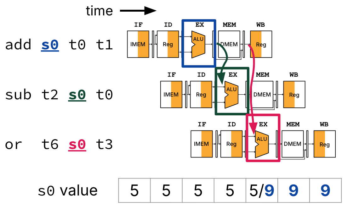
Figure 3:Forwarding adds extra connections between pipeline registers and other components in the datapath.
Notes:
At the beginning of cycle 4, the ALU result from the
addinstruction is forwarded from itsEX/MEMpipeline register directly to the ALU (for thesubinstruction’sEXstage).At the beginning of cycle 5, the ALU result from the
addinstruction is forwarded from itsMEM/WBpipeline register directly to the ALU (for theorinstruction’sEXstage).The value of register
s0is still updated in cycle 5, from the stale value 5 to the new value 9. TheIDstages of thesubandorinstructions still read the stale value of registers0in cycles 2 and 3, respectively. What matters is that the correct operands are fed into ALU during theEXstage for both of these instructions.Note that with hardware forwarding, we do not need to update the waterfall diagram in Table 5 because no stalls occur.
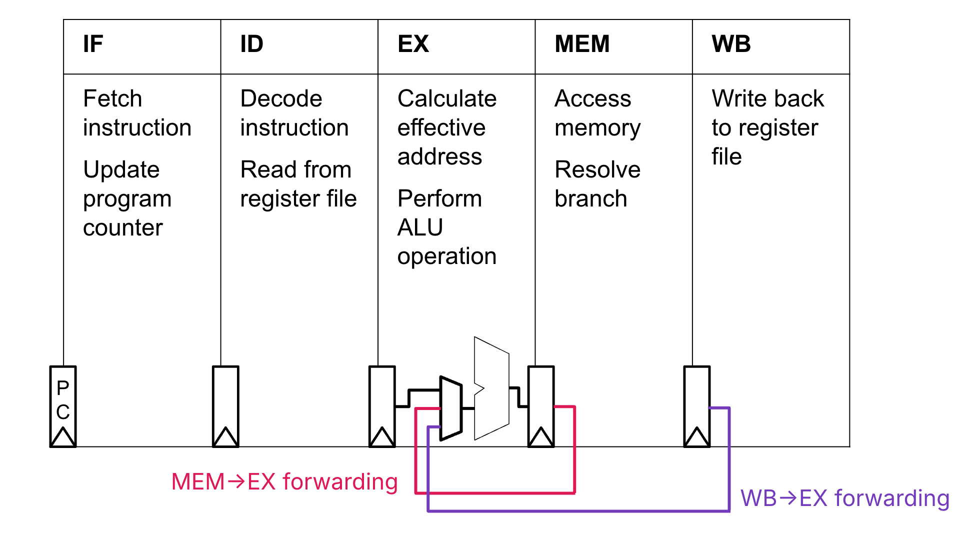
Figure 4:Forwarding bypasses for the ALU’s B input signal. For simplicity, we do not draw the bypasses for the A input signal, though they are certainly needed. With the exception of the PC, registers between stages are pipeline registers. Adapted from Spring 2026 CS 152.[7]
Show Answer
We do not need to stall the pipeline. The ALU result from the add instuction is available at the beginning of cycle 4. We can leverage the MEM to EX forwarding path to forward the add instruction’s ALU result directly from the EX/MEM pipeline registers to the ALU for the sub instruction’s EX stage, also in cycle 4.
4.1Implementing Forwarding
Forwarding is implemented by adding bypass wires between pipeline registers and other components, inserting muxes, and including additional control logic.
Figure 6 shows an implementation of the MEM to EX forwarding path. The forwarding path (e.g., bypass) connects the output of the ALU from the EX/MEM pipeline register to the ALU input muxes. These two muxes are now wider to account for the additional bypass option. The control signals ASel and BSel now must also use the instruction bits to determine if the bypass should be used for either input to the ALU.
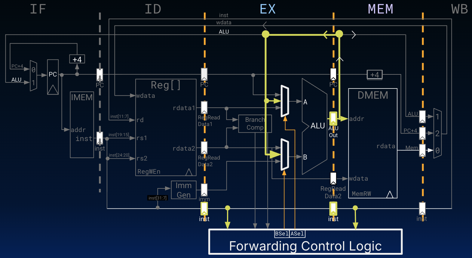
We omit the full MEM/WB forwarding circuitry, leaving this for you to work out.
Show Answer
A. The
add-lwdata hazard is resolved byMEMtoEXforwarding. Theaddinstruction result (of addingt1andt2) is available in theEX/MEMpipeline registers at the beginning of cycle 4. Cycle 4 is also thelwinstruction’sEXstage. In this cycle, the correct value is forwarded from theEX/MEMpipeline registers to the A input of the ALU, overriding the stale value of registers0fetched during thelwinstruction’sIDstage in cycle 4.C. The
lwanddata hazard is resolved byWBtoEXforwarding. The memory read result from thelwinstruction is available from theMEM/WBpipeline registers at the beginning of cycle 6. Cycle 6 is also theandinstruction’sEXstage. In this cycle, the correct value is forwarded from theMEM/WBpipeline registers to the A input of the ALU, overriding the stale value of registers1fetched during theandinstruction’sIDstage in cycle 5.
The lw-or data hazard in option B is not resolved by the proposed forwarding logic. Cycle 5 is the or instruction’s EX stage. However, the lw instruction does not finish reading the value from DMEM (to be loaded into register s1) until the end of cycle 5. The result of this memory read is not available in the MEM/WB pipeline registers until cycle 6.
5Load Data Hazards
The lw-or data hazard described above is an example of a load-use data hazard. The hazard stems from an instruction’s EX stage depending on a memory read from an immediately preceding load instruction’s MEM stage in the same clock cycle.
5.1Approach 1: Stall
Consider the instruction sequence in the previous Quick Check. As shown in Table 7, the pipeline must stall for one cycle to avoid the lw-or data hazard.
Table 7:With a hazard detection unit in the ID stage, a bubble is inserting beginning in cycle 5, changing the or instruction to a nop. The or instruction is fetched and decoded in cycles 3 and 4, but its EX stage is delayed until clock cycle 6.
Instruction | 1 | 2 | 3 | 4 | 5 | 6 | 7 | 8 | 9 |
|---|---|---|---|---|---|---|---|---|---|
| IF | ID | EX | MEM | WB | ||||
| IF | ID | EX | MEM | WB | ||||
| IF | ID | — | — | — | ||||
| IF | ID | EX | MEM | WB | ||||
| IF | ID | EX | MEM | WB |
5.2Approach 2: Code scheduling
Consider the instruction sequence in the previous Quick Check. We observe that if the or and sll instructions were switched, we could avoid the inevitable stall due to the potential lw-or data hazard.
From P&H 4.8:
Although the compiler generally relies upon the hardware to resolve hazards and thereby ensure correct execution, the compiler must understand the pipeline to achieve the best performance. Otherwise, unexpected stalls will reduce the performance of the compiled code.
In other words, if the compiler knows how the processor resolves data hazards, it can design instruction sequences to avoid unavoidable stalls, e.g., due to loads. This approach is called code scheduling. With knowledge of the underlying processor architecture, the compiler reorders code to improve performance.
Consider the below C code.
A[3] = A[0] + A[1];
A[4] = A[0] + A[2];
Suppose that the address of array int A[] is in register a0 and the 0th to 4th elements of A are in t0 through t4, respectively.
A simple compilation would result in inevitable stalls due to instructions in the load delay slots needing the load results. If the pipeline implements WB to EX forwarding, stalling incurs two additional cycles, as below.
lw  t0 0(a0)
lw  t1 4(a0)
add t2 t0 t1    # stalled one cycle
sw  t2 12(a0)
lw  t3 8(a0)    # stalled one cycle
add t4 t0 t3
sw  t4 16(a0)
A compiler could use code scheduling by inserting instructions into the load delay slots that are unrelated to the load results. With forwarding, the new seven-instruction sequence below does not incur any performance loss due to stalling.
lw  t0 0(a0)
lw  t1 4(a0)
lw  t3 8(a0)
add t2 t0 t1
sw  t2 12(a0)
add t4 t0 t3
sw t4 16(a0)6Summary: Detecting Data Hazards and Implementing Forwarding
Again, data hazards occur between different stages, when an instruction reads a register before a previous instruction has finished writing to the same register.
Suppose we have the rs1, rs2, RegWEn, and rd signals for two instructions (instruction n and instruction n + 1) and we wish to determine if a data hazard exists between the instructions. We can check to see if register rd for instruction n matches either register rs1 or rs2 of instruction n + 1, indicating a data hazard.
We could then use our hazard detection to determine which forwarding paths/number of stalls (if any) are necessary to take to ensure proper instruction execution. In pseudocode, part of this could look something like the following:
if (rs1(n + 1) == rd(n) && RegWen(n) == 1) {
    set ASel for (n + 1) to forward ALU output from n
}
if (rs2(n + 1) == rd(n) && RegWen(n) == 1) {
    set BSel for (n + 1) to forward ALU output from n
}
Read P&H 4.8 for more information.
How do we check destination registers? The hazard detection unit checks the pipeline registers. For example, if register
rdspecified in theID/EXpipeline registers is one of the source registers for the instruction in theIDstage, then stall the instruction in theIDstage.This is somewhat of an overstatement; read P&H 4.9 for more details.
If the instruction in the
IDstage is stalled, then the instruction in theIFstage must also be stalled, etc. We can accomplish this by (1) preventing the PC register from incrementing, and (2) preventing theIF/IDpipeline register from changing. From P&H 4.8: “It’s as if you restart the washer with the same clothes, and let the dryer continue tumbling empty. Of course, like the dryer, the back half of the pipeline starting with the EX stage must be doing something; what it is doing is executing instructions that have no effect: nops.”We note this hazard is not a structural hazard. After all, the RegFile design does not prevent
addandswfrom reading/writing to the same register in the same cycle, because there are sufficient input ports. However, what is concerning is that the valueswreads must be the correct value thataddwrites.From P&H 4.6: “The name forwarding comes from the idea that the result is passed forward from an earlier instruction to a later instruction. Bypassing comes from passing the result around the register file to the desired unit.”
Original diagram by Wen Cao, Spring 2026 CS 152/252 TA. The CS 152/252 diagram is for a different pipelined datapath with different forwarding paths (e.g., see the MUX into the ID/EX pipeline register). Please use Figure 4 for this course.