1Learning Outcomes
Understand tradeoffs between integer representations:
(unsigned) integers
(signed) Sign-Magnitude
(signed) Ones’ Complement
Bias Encoding
Identify when and why integer overflow occurs
Perform simple binary operations like addition
🎥 Lecture Video
2Introduction
Historically, computers were used as scientific calculators. We therefore dedicate most of our time to understanding how a string of bits (a bit string) can represent a number.
How can we use bits to represent a set of integers?
There are many systems we can use. Not all systems will help us represent unique integers in bits! We will focus on representing signed and unsigned integers.
Signed integers refer to positive integers, negative integers, and zero.
Unsigned integers refer to non-negative integers, i.e., at least greater than zero.
3-bit Unsigned Integer Representation
Let’s get our standard unsigned integer representation out of the way first. The mathematical scheme discussed earlier is sufficient for representing unsigned integers with bits.
0b0...0( zeros) represents zero0b1...1( ones) represents (why?)Everything else: Assume the bitstring is the base-2 representation of a number. Convert.
This representation is supported in C (discussed more later). Built-in types like unsigned int can introduce ambiguity because it doesn’t specify the width of an int. The header inttypes.h accommodates typedefs like uint8_t, uint16_t, uint32_t, etc. to specify unsigned integer representations that are 8-bit, 16-bit, 32-bit etc.
4Design Considerations
We will prefer certain systems over others, depending on what sorts of integer operations we want to support.
4.1Common number operations
In decimal, we like to add, subtract, multiply, divide, and compare numbers. So we must be able to do the same thing with bit representations of numbers.
It turns out that many arithmetic operations translate reasonably well between decimal and binary.
For example, let’s add 10 and 7, which are 1010 and 0111, respectively, in binary. The result is the number 17, or 10001 in binary.
Explanation
Work right-to-left:
0+1=11+1=0carry11+0+1=0carry11+0+1=0carry11
(Double check that binary math matches decimal math: )
Subtraction in binary works similarly. We leave an in-depth discussion of implementing binary comparison (e.g., ) to a future project.
4.2The Odometer Analogy
In theory, numbers have an infinite number of digits (usually leading zeros), but in computing, we must allocate a finite number of bits. Hardware is limited! Binary bit patterns are therefore abstractions: they are simply representatives of numbers.
In choosing an integer representation, we must consider whether the operations supported will still work within the given bit width of an integer representation. One useful analogy for considering edge cases comes from the idea of an odometer:
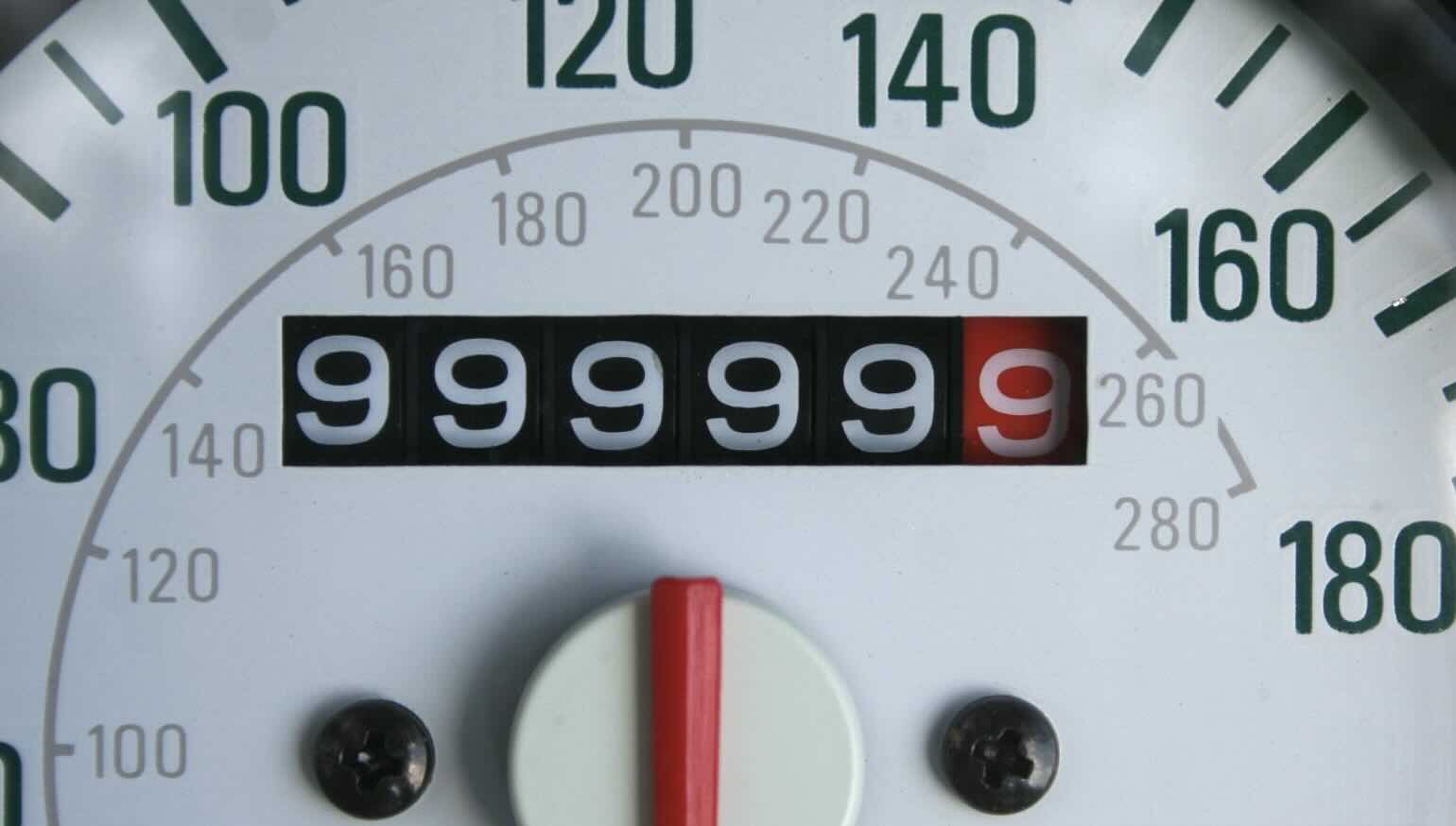
Figure 1:A car odometer measures mileage. It starts at 0 and slowly ticks up, then wraps around again. At some point, the odometer above will hit 999999; the next number is again 0.
Two sets of values to consider:
The binary values
000...000,000...001,000...010, ...,111...111Integers incrementing by one, as placed on a number line
As we will see, there are systems in which the “directions” of these values may diverge.
4.3Integer Overflow
Integer overflow: The arithmetic result is outside the representable range of integers.
Suppose we use bits to represent integers in hardware. If the result of an integer operation (, etc.) cannot be accurately represented in bits, we say that integer overflow occurred.
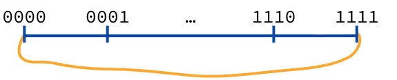
Figure 2:With unsigned integers, the “binary odometer” wraps around.
4-bit unsigned integers: Using 4 bits, you can represent 0 through 15.
Positive Overflow: If you are at 15 (
0b1111) and add 1, the value wraps around to 0 (0b0000).Negative Overflow: If you are at 0 (
0b0000) and subtract 1, it wraps around to 15 (0b1111).
4.4-bit Signed Integer Representations
How do you represent negative numbers? More generally, how do you represent both positive and negative numbers (and zero) with the same bits?
Sidebar: There was a king who asked his wise thinkers to teach him economics. They kept bringing him long books, and he kept sending them away to make it shorter. Finally, they came back and said, "Sire, we have the theory of economics in four words: ‘Ain’t No Free Lunch.’ " It means you can’t get something for nothing.
If we want to represent negative numbers, you’ve got to give something up; you lose some of the positive numbers you used to have. If we borrow a bit, we can’t go as high in the positive range, but now we can do negatives.
Next, we discuss a few reasonable ones and consider tradeoffs. In the next section, we’ll reveal the standard representation used in modern architectures and supported by the C23 standard.
5Sign-Magnitude
Leftmost sign bit: the integer’s sign.
0is positive;1is negative.Rest of bits: magnitude of the integer in binary
4-bit Sign-Magnitude
Positive numbers: 1 (
0b0001) to 7 (0b0111)Negative numbers: -1 (
0b1001) to -7 (0b1111)Two zeros: +0 (
0b0000) and -0 (0b1000)
We already see one problem! With a positive and a negative zero, we’d have to check for two different patterns in code, every time we want to compare values to zero.
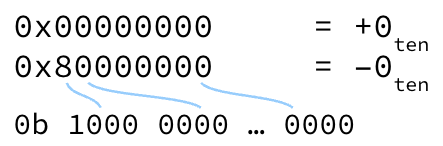
Figure 3:Sign-Magnitude has two representations for zero: “positive zero” and "negative zero.
Let’s examine a subtler problem, revealed via the binary odometer:
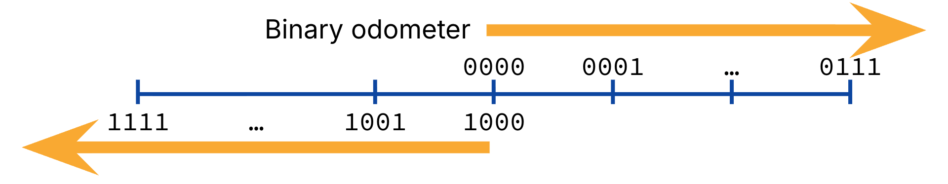
Figure 4:“Binary odometer” for 4-bit sign-magnitude.
The problem with Sign and Magnitude is that as the odometer goes up, it goes the wrong way: you go positive, positive, and then suddenly you hit the negative range. Incrementing the binary odometer 0000 to 1111 starts at 0, then 1, through to 7, then wraps to 0 again, then -1, then -7. In other words, sometimes integer addition corresponds to adding bits, and sometimes integer addition corresponds to subtracting bits. This would get complicated very quickly!
Further Explanation
Consider adding with 4-bit sign-magnitude integers.
+5:
0101-5:
1101
If both numbers have the same sign, we keep the sign and peform addition on the magnitudes, accounting for overflow where needed. In this case, the numbers have different signs, so we would have to perform subtraction on the magnitudes. Arithmetic addition is conditional in this representation–it can either be binary addition or subtraction–and circuitry would be more complicated.
Ultimately, Sign-Magnitude is considered a straw man[1] approach for supporting general purpose computing with integers. Nevertheless, it has some reasonable applications in, say, signals processing, where users are more commonly looking to decouple sign from magnitude, much less add numbers together. Ask us for more.
6Ones’ Complement
To represent a negative number, complement the bits of its positive representation.
Here, “complement” means that if the bit is 0 change it to 1, and vice versa. Equivalently, to change the sign of a number, flip all bits of its binary representation.
-7 with 8-bit Ones’ Complement
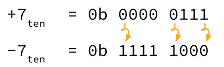
Figure 5:Ones’ complement: To change sign, flip the bits.
Start with representing +7:
0b 0000 0111(we add the spacing and the prefix for better visualization, but the actual bitstring is00000111)Flip all bits:
0b 1111 1000(again, actual bitstring is11111000) This is the representation of -7.
We’ve fixed one problem. We still get integer overflow, sure, but at least incrementing the binary odometer now corresponds to integer addition by one in most places of the timeline.
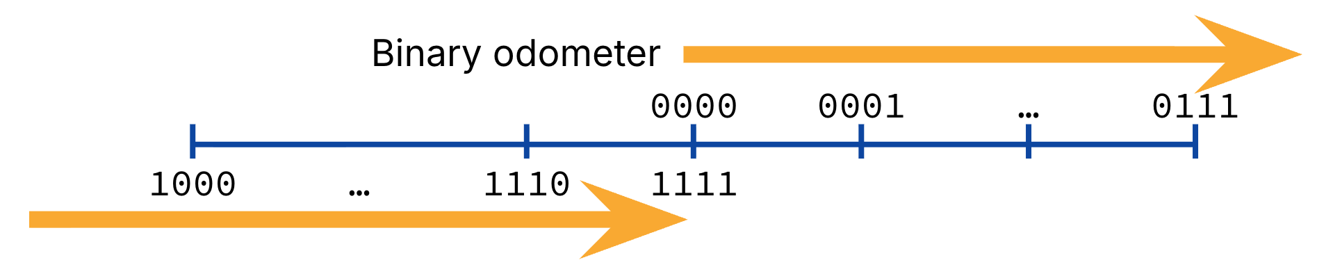
Figure 6:“Binary odometer” for 4-bit ones’ complement.
Further Explanation
Consider adding with 4-bit one’s complement integers.
+5:
0101-5:
1010
Addition: 0101 + 1010 = 1111, or -0. Arithmetic addition can be implemented with binary addition, regardless of operand sign.
::{note} Further Explanation :class: Dropdown
Consider adding with 4-bit one’s complement integers.
+5:
0101-5:
1010
Addition: 0101 + 1010 = 1111, or -0. Arithmetic addition can be implemented with binary addition, regardless of operand sign.
:::{tip} Quick Check

Suppose you interpret an N-bit pattern as a Ones' Complement integer. How do you determine if the bit pattern represents a positive number? a negative number?
Show Answer
Positive numbers: leading 0s
Negative numbers: leading 1s
Show Answer
Zero: 2
Positive:
Negative: (same as positive)
Another added benefit of Ones’ Complement
The leftmost bit (also known as most significant bit) is still effectively the sign bit.
...But we still have the problem of two zeros.
Historically, this was used for a while, but eventually abandoned for two’s complement.
7Bias Encoding
Bias Encoding:
Keep track of a bias.
To interpret stored binary: Read the data as an unsigned integer, then add the bias
To store an integer as data: Subtract the bias, then store the resulting number as an unsigned integer.
Imagine you are recording an electrical signal wavering between 0 and 31 volts. Wouldn’t it be cool to grab that graph and pull it down so it wiggles around zero? That’s bias encoding.
We can shift to any arbitrary bias we want to suit our needs. To represent (nearly) as much negative numbers as positive, a commonly-used bias for -bits is .
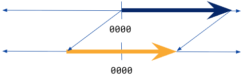
Figure 7:A bias-encoded representation effectively shifts the number line to an unsigned representation.
Example: with bias
5-bit integer representation
Bias:
All zeros: smallest negative number
Here are some diagrams in case they are useful. Figure 8 represents a bias encoding where and bias . The odometer just does the right thing; it counts up through zero with nothing strange happening.
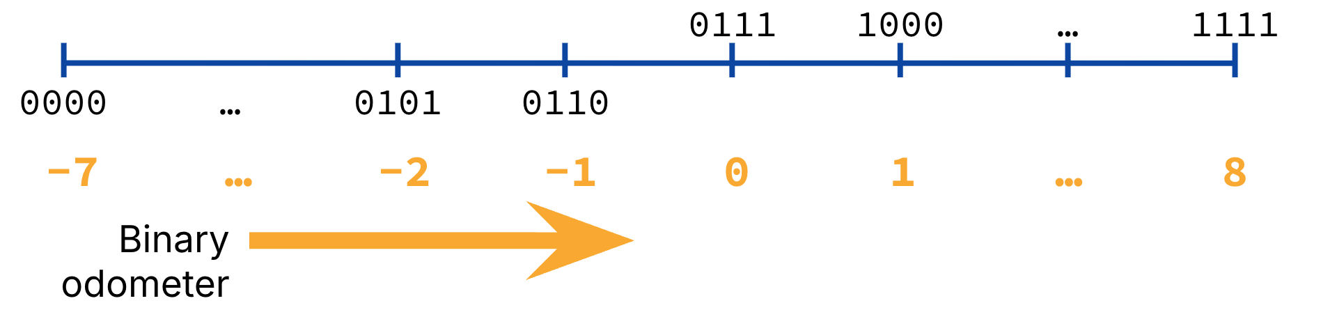
Figure 8:“Binary odometer” for 4-bit bias-encoded integers, with bias -7.
You may also find the number wheel useful for seeing where overflow happens, and how integers increase with respect to binary incrementing. See Figure 9.
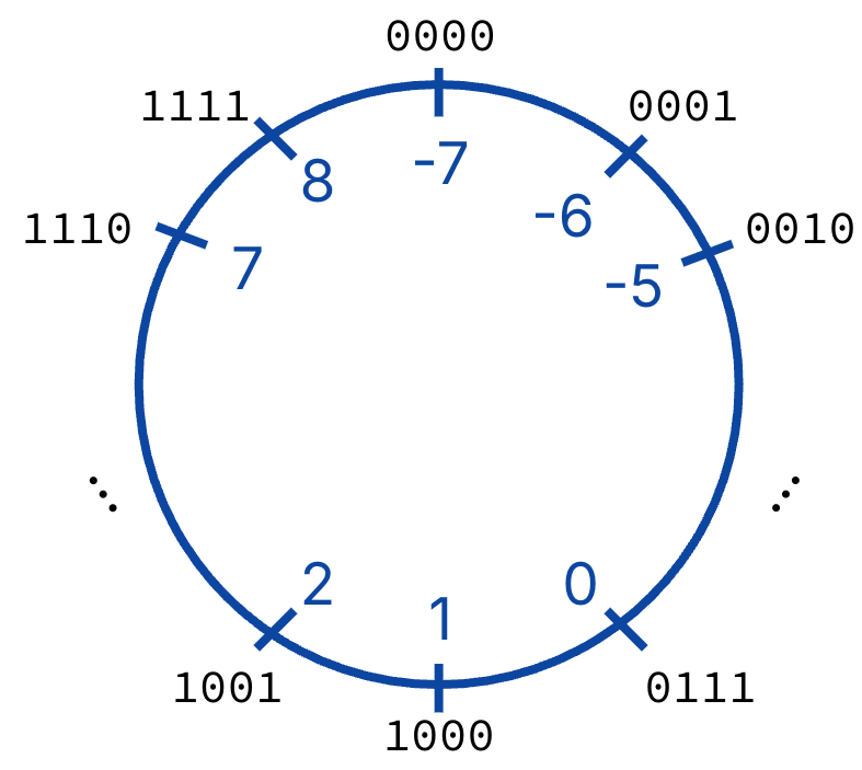
Figure 9:Number wheel for bias encoding.
We really like biased encoding for some specific applications we’ll see later in the course.