1Learning Outcomes
Identify an instruction format type by the
opcodefield.Translate between R-type assembly instructions and machine instructions.
🎥 Lecture Video
Like with IEEE 754 floating point numbers, the 32 bits of a machine instruction are split into fields. Like floating point, each field has a name and occupies a given set of bit positions (and therefore has a fixed width). Unlike floating point, the field names and locations themselves depend on the instruction type.
As an example, an R-type instruction is shown in Figure 1. The field named opcode occupies the least-significant bits (bit positions 0 to 6); the opcode field is 7 bits wide. Also notice that the assembly instruction opname rd rs1 rs2 shares some nomenclature with instruction fields, but not all. For example, rs1, rs2, and rd are field names, but opname is not.
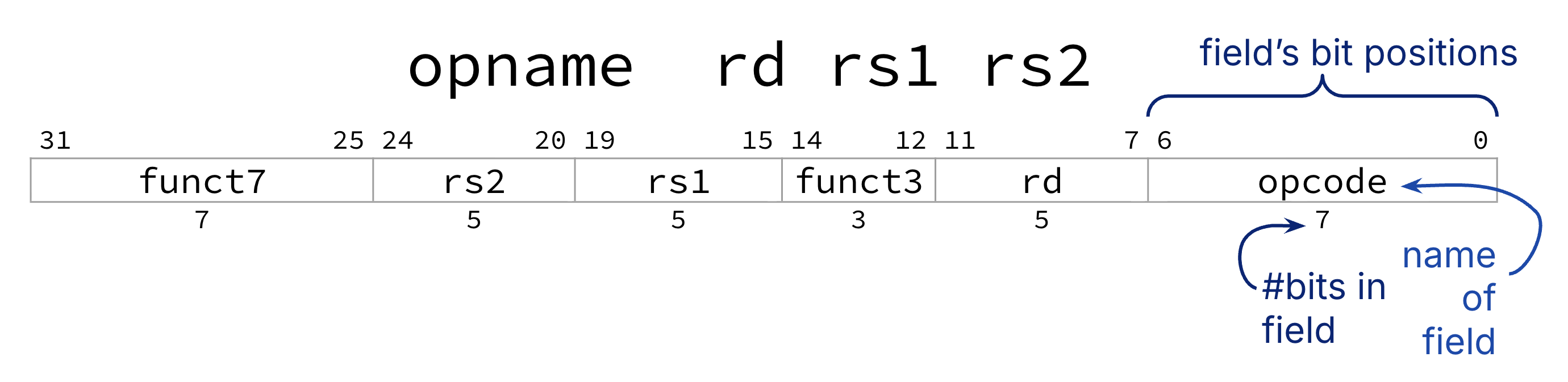
Figure 1:Field names and locations depend on the instruction format.
2R-Type: Fields
The R-Type instruction format is the first row of the instruction format table of the RISC-V green card. All register-register arithmetic instructions use R-Type (the “R” is for Register). We now use “arithmetic” to encompass arithmetic and bitwise operations: add, xor, sll, etc.
We recommend you reference the arithmetic instructions table as you explore the R-Type instruction format below.
Figure 2 (Figure 1 with less annotation) shows the R-Type format. Notice that all register-register arithmetic instructions have follow the same assembly instruction syntax opname rd rs1 rs2.
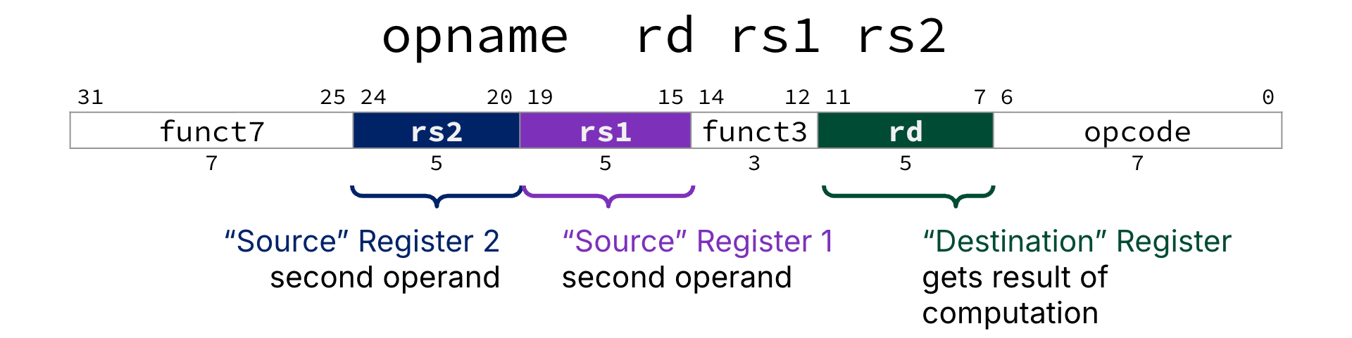
Figure 2:The R-Type Instruction Format.
Register operands: The three R-Type fields named rs1, rs2, rd map to their equivalent assembly instruction operands. Each field is a 5-bit unsigned integer (0 to 31) corresponding to a register number (x0-x31). Register names (e.g., a0) are translated first into their register number (e.g., x10), then their bit pattern (e.g., 01010).
rs1: “Source” Register, first operandrs2: “Source” Register, second operandrd: “Destination” Register gets the result of the arithmetic computation.
Other fields: The assembly instruction operation opname is mapped across three fields: `
opcode: All R-type instructions have the same 7-bit opcode:0110011.funct3,funct7: The arithmetic operation to perform.funct3field is 3 bits wide;funct7is 7 bits wide.
3Assembly Instruction Machine Instruction
Consider Figure 3, which translates add x18 x19 x10 to a machine instruction.
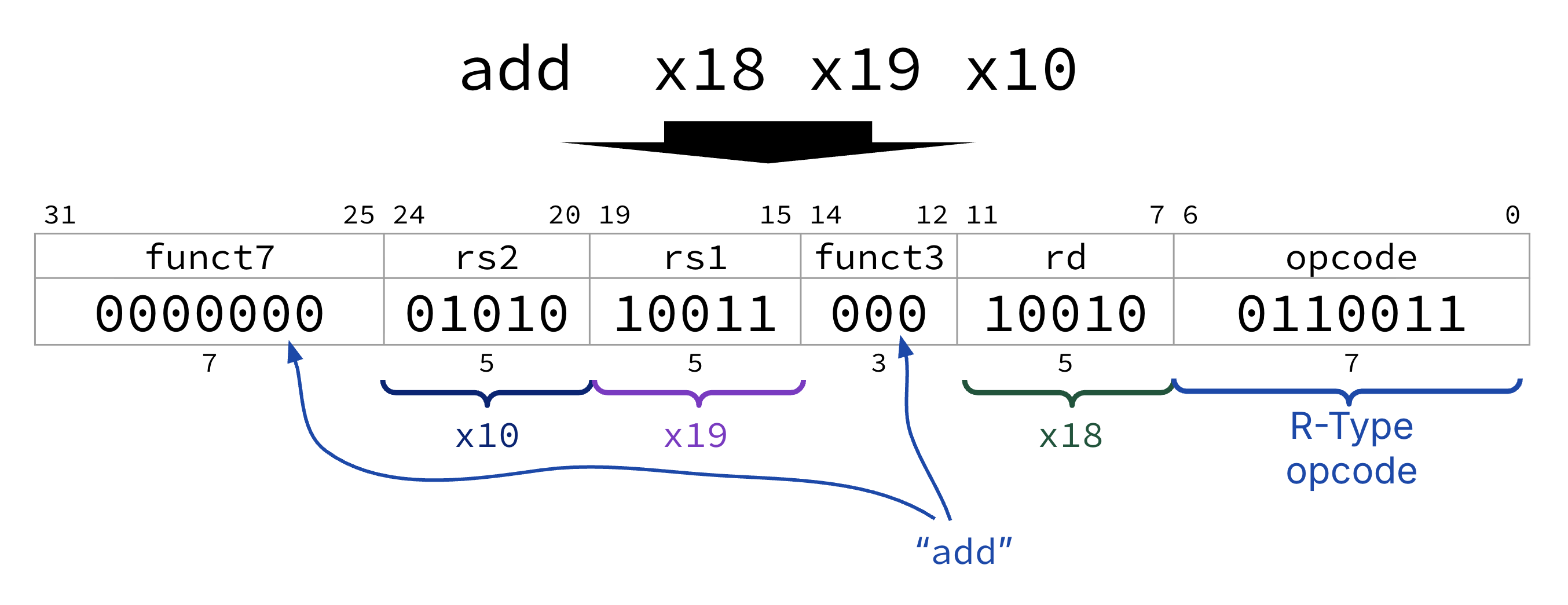
Figure 3:The R-Type instruction add x18 x19 x10.
Determine instruction format type.
addis R-type because it performs arithmetic on two register operands. We use the arithmetic instructions table on the RISC-V green card.Determine operation field codes.
opcode:0110011(for all R-Type instructions).funct3:000foraddfunct7:0000000foradd
Translate registers, immediates, etc.
rs1: Registerx19. Translate 19 to 5-bit unsigned integer representation10011.rs2: Registerx10. Translate 10 to 5-bit unsigned integer representation01010.rd: Registerx18. Translate 18 to 5-bit unsigned integer representation10010.
(if needed) Convert to hexadecimal.
We leave this as an exercise to you!
4Machine Instruction Assembly Instruction
Steps for translating machine code into assembly:
If needed, convert to binary. Then, find the opcode and use that to determine the instruction format type.
Split into fields according to instruction format type.
For R-Type, determine the assembly instruction
opnamewith thefunct3,funct7fields.For R-Type, determine register operands and (if needed) register names.
The last two steps are R-Type-specific. In general, you should always do the first two steps, regardless of instruction format type. Then, perform type-specific conversions to reconstruct the original assembly instruction.
Show Answer
E. xor t0 t1 s11
Explanation:
We have already converted
0x01B342B3to binary:0b0000 0001 1011 0011 0100 0010 1011 0011.Then, find the opcode and use that to determine the instruction format type. The
opcodefield is always the lowest 7 bits of the instruction, regardless of format.0110011is the opcode for R-Type instructions.Split into fields according to instruction format type.. For translation, it is not particularly useful to visually space out nybbles, as above. In Figure 4, the 32-bit pattern above is visually split into the six fields of the R-Type instruction format.
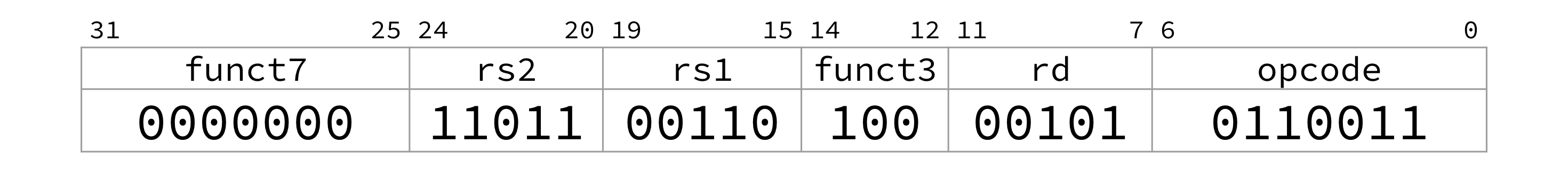
Figure 4:Once an instruction’s type is known, the instruction bits can be mapped to fields.
Determine the assembly instruction
opname. Thefunct3field is100; thefunct7field is0000000. We look up these fields on our green card and discover the instruction isxor.Determine registers. Use the register convention table for register names.
rd:10010is 5, so registerx5, akat0.rs1:00110is 6, so registerx6, akat1rs2:11011is 27, so registerx27, akas11.
Given the above, the instruction is E. xor t0 t1 s11.
5Design Decisions for R-Type
Consider all 10 R-Type instructions shown in Table 1, which is a reformatting of the rightmost columns of the equivalent table on the RISC-V green card.
Analyze this table. What do you notice? What do you wonder? The below discussion questions practice the following:
Read and interpret instruction fields
Develop your design intuition for architecture.
Table 1:RV32I Instructions: R-Type
| Instruction | funct7 | rs2 | rs1 | funct3 | rd | opcode |
|---|---|---|---|---|---|---|
add | 0000000 | rs2 | rs1 | 000 | rd | 0110011 |
sub | 0100000 | rs2 | rs1 | 000 | rd | 0110011 |
and | 0000000 | rs2 | rs1 | 111 | rd | 0110011 |
or | 0000000 | rs2 | rs1 | 110 | rd | 0110011 |
xor | 0000000 | rs2 | rs1 | 100 | rd | 0110011 |
sll | 0000000 | rs2 | rs1 | 001 | rd | 0110011 |
srl | 0000000 | rs2 | rs1 | 101 | rd | 0110011 |
sra | 0100000 | rs2 | rs1 | 101 | rd | 0110011 |
slt | 0000000 | rs2 | rs1 | 010 | rd | 0110011 |
sltu | 0000000 | rs2 | rs1 | 011 | rd | 0110011 |
Show Explanation
One opcode for all R-Types: 0110011.
Show Explanation
funct3: 8 unique, despite there being 10 instructions.funct7: 2 unique. The remaining two instructions vary infunct7fields.
Show Explanation
funct3field000:addandsub. To differentiate, look atfunct7field.subhas a1in bit 30, whereasadddoes not.
funct3field101:srl,sra. To differentiate, look atfunct7field.srahas a1in bit 30, whereassrldoes not.