1Learning Outcomes
Understand how the program counter (PC) register updates between instructions.
Understand how the processor uses the PC to determine which instruction to load and execute.
🎥 Lecture Video
So far, we have seen that during execution, values are stored in registers. Assembly instructions operate on registers and load/store values between registers and memory.
We discuss the basics of the RISC-V memory model across the next two chapters.
2Stored Program, Revisited
In an earlier section we discussed the concept of the stored-program computer, which is effectively used for all general-purpose computers today:
Data doesn’t just have to represent numbers; it can represent the program itself.
[1] Recall that assembly language is typically produced by a compiler. An assembler then produces the machine-readable code. Typically, this is stored as an executable file, which is then loaded in to the text segment of memory:
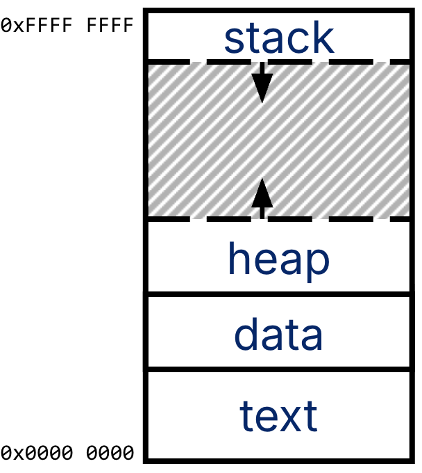
The C memory layout (reprint of Figure 1 from this section).
RISC-V has a similar memory model. Each RISC-V assembly instruction is stored as machine code, i.e., bits. Each assembly instruction translates to a 32-bit machine instruction (in RV32I, our word size is 32 bits). For example, the instruction slli x12 x10 0x10 translates to the bits 0x01051613.[2]. These 32-bit machine instructions then compose the machine code executable file.
The machine code executable is too large to fit in registers, so it resides in memory (in C, this would be the text segment). The program itself is essentially a sequence of RISC-V instructions, each 32 bits wide, which are usually executed in order until the processor hits a branch or a jump.
3The Program Counter (PC)
How does a computer know which instruction to execute? The processor also keeps track of this value in a register! From the RV32I Specification:
There is one additional unprivileged register: the program counter
PCholds the address of the current instruction.
The Program Counter (PC[3]) is effectively a pointer to memory[4] and is a register named pc[^pc-name]. The pc register is not one of the 32 registers numbered x0 to x31. It is a separate register that generally is not explicitly specified as a read/write destination for instructions.
[^pc-name] Verilog syntax is PC, though the RISC-V Unprivileged Manual calls it pc.
We revisit our conceptual computer layout from earlier and focus on the program counter in Figure 2.
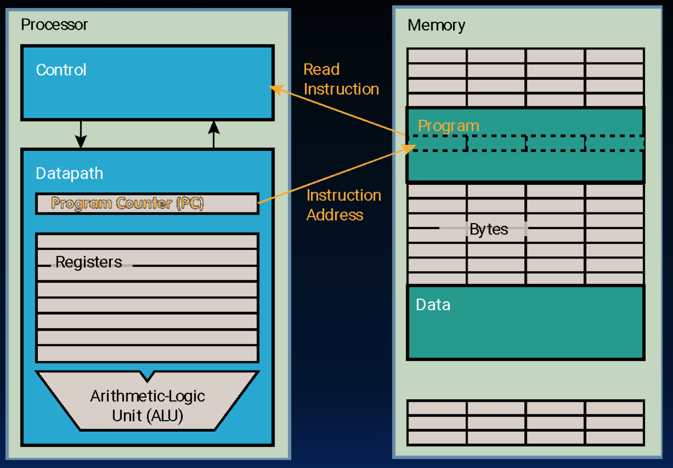
Figure 2:The program counter holds the address of the current instruction.
The processor on the left consists of a control unit and a datapath. The memory sits on the right. Inside the datapath, we have our 32 registers and our PC, which is a register internal to the processor that holds the byte address of the next instruction ot to be executed.
The control unit[5] uses the PC as follows:
Read the PC,
Fetch an instruction from memory,
Execute the instruction using the datapath, and
Update the PC to point to the next instruction.
3.1Example: Arithmetic Instruction
The below animation traces through a toy example of how a executing arithmetic instruction updates both the destination register and the program counter register.
Above, the processor executes one instruction as follows:
The processor reads
pc, which currently holds0x00000008.The processor reads the instruction in memory at address
0x00000008, which isslli x12 x10 0x10.The processor executes this instruction by reading and writing registers. If
x10holds0x0000 34FF, thenx12is updated to0x34FF0000.The processor updates
pcto hold0x00000008 + 4, or0x0000000c.
Certain instructions will request that the PC be updated differently. These instructions are called branches and cause a completely new address to be loaded into the PC. This is the topic of the next two chapters.
We expand on the compiler-assembler-linker-loader process in a later section.
We see how to do this translation later.
Program Counter, not Personal Computer.
Intel calls the program counter an Instruction Pointer (PC).
We discuss the control unit later when we design our processor. For now, we introduce the program counter to explain the full set of assembly instructions.