1Learning Outcomes
Using terminology, describe how to find a block in a fully associative cache: address, tag, and offset.
Explain why a valid bit is needed for cache design.
Compare different block replacement policies: LRU, FIFO, and random.
Compare two write policies: write-through and write-back. Optimize the latter with a dirty bit.
For a given pattern of memory accesses, identify if each memory access is a cache hit or cache miss.
🎥 Lecture Video: Fully Associative
🎥 Lecture Video: Block Replacement
Until 7:00. The example assumes familiarity with set associative caches, a placement policy we discuss in a later section
🎥 Lecture Video: Writes
Until 13:00
🎥 Lecture Video: Block Size
Until 22:45
How do we design a cache? From earlier:
In this section, we introduce the fully associative cache and use it as a means to discuss a detailed example and tradeoffs between replacement policies and write policies.
2Placement policy
Associativity refers to the possible entries that a particular block of data can be associated with.
3Identification
How do we determine a cache hit on a memory address? In other words, how do we know if the data at a specific memory address can be accessed from a block in the cache? From Computer Organization: A Quantitative Approach Appendix B.1:
Caches have an address tag on each block frame that gives the block address. The tag of every cache block that might contain the desired information is checked to see if it matches the block address from the processor. As a rule, all possible tags are searched in parallel because speed is critical.
There is a lot in this paragraph.[1] We first explore the relationship between a memory address and the tag of a cache entry. We then explain how we determine cache hits.
3.1Tag and Offset
We would like to connect the blocks in to the cache shown in Figure 1, which is a 16B fully associative cache with 4B blocks, to the 12-bit memory address in Figure 2. We do so by splitting the address into two portions: tag and offset.
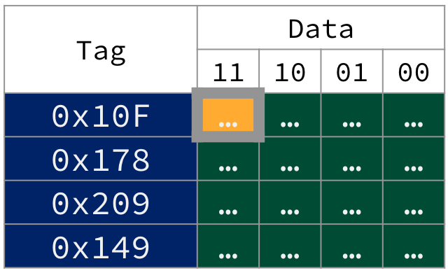
Figure 1:Cache tag and offset in a 16B fully associative cache for 12-bit memory addresses. The bytes in the first entry’s block share the same upper 10 bits of their memory addresses: 0b0100001111, or 0x10F, which is the tag. The address of the most significant byte in the first block is therefore 0x43F.
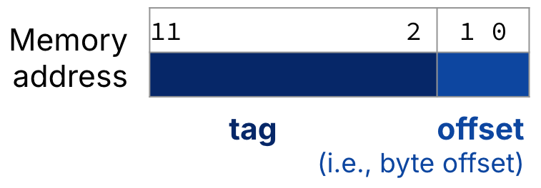
Figure 2:For a fully associative cache, the memory address is split into two fields: the tag and the offset. For the blocks in Figure 1, a 12-bit memory address is split into a 10-bit tag and a 2-bit offset.
What then, is a tag? Recall that all of the bytes in each block of data are from the same area of memory. Their address will share a common set of upper bits. In fully associative caches like in Figure 1, all of these upper bits are placed into the tag associated with each block.
What about the offset? Memory is byte addressable, so each of the bytes in a given block will have different memory addresses. The memory addresses of bytes in a given block will not vary in the upper bits (the tag) but rather in the lowest bits. The offset is the portion of the address needed to describe this variation.
More explanation of Figure 1
Consider the addresses of each of the four bytes of the first cache block (with tag 0x10F):
Least significant byte (rightmost in first block of Figure 1 cache) has byte offset
0b00. We reconstrruct the memory address by prepending the 10-bit tag0x10Fto the offset to get0b01 0000 1111 00, or0x43C.Second least significant byte has offset
0b01. Prepend the same 10-bit tag0x10Fto get0b01 0000 1111 01, or0x43D.Second most significant byte has offset
0b10. Binary address0b01 0000 1111 10, or0x43E.Most significant byte (leftmost and highlighted in first block of Figure 1 cache) has offset
0b11. Binary address0b01 0000 1111 11, or0x43F.
3.2Valid bit
There must be a way to know that a cache block does not have valid information. For example, when starting up a program, the cache necessarily does not have valid information for the program. The most common procedure is to add an indicator (i.e., flag) to the tag to tell if each entry in the cache is valid for this particular program.
The valid bit indicates if the tag for the block is valid. If the valid bit is set (1), the tag refers to a valid memory address. If it is not set (0), we should not match to this tag (even if the tag bits match by chance).
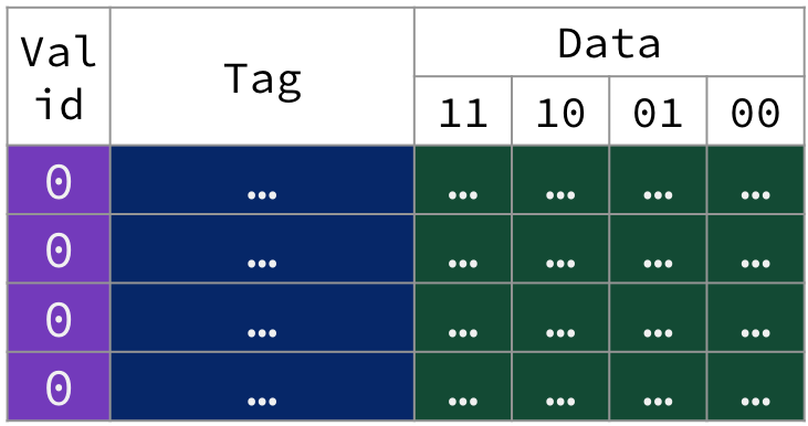
Figure 3:A cold snapshot of the fully associative cache in Figure 1, where valid bits for all blocks are unset (i.e., set to 0). We illustrate the valid bit in our tabular visualization as an additional column of metadata.[2]
4Walkthrough: Warming up the Fully Associative Cache
The following animation traces through five memory accesses to a 12-bit address space on our 16B fully associative cache with 4B blocks. Assume the cache starts out cold, like in Figure 3.
Figure 4:Warming up a fully associative cache.
To keep things simple for now, if we encounter a cache miss, we load the new block from memory into an invalid cache entry. We discuss block replacement policies in the next section.
1. Load byte @ 0x43F. Cache miss.
0x43F. Cache miss.Address 0x43F in binary: 0b0100 0011 1111
Tag:
0b0100001111, or0x10FOffset:
0b11
Cache Miss. No valid tags in the cache match
0x10F.Access lower level of memory hierarchy. Load into a selected cache entry a block’s worth of data from memory starting @ address @
0x43C. Write the tag0x10F. Mark valid bit.Spatial locality: Even if we only read in one byte, loading from memory will load the full block (here, 4B), where all bytes of data in the block share the same tag because they are from the same region of memory:
Least significant byte in block (offset
0b00) is @ memory address0x43C(0b0100 0011 1100)Most significant byte in block (offset
0b11) is @ memory address0x43F(0x0b100 0011 1111)
Read. Read byte in cache block at offset
0b11(i.e., most significant byte in block) and return to processor.
2. Load byte @ 0x5E2. Cache miss.
0x5E2. Cache miss.Address 0x5E2 in binary: 0b0101 1110 0010
Tag:
0b0101111000, or0x178Offset:
0b10
Cache Miss. No valid tags in the cache match
0x178.Access lower level of memory hierarchy. Load into a selected cache entry a block’s worth of data from memory starting @ address
0x5E0(0b0101 1110 0000). Write the tag0x178. Mark valid bit.Read. Read byte in block at offset
0b10and return to processor.
3. Load word @ 0x824. Cache miss.
0x824. Cache miss.Address 0x824 in binary: 0b1000 0010 0100
Tag:
0b1000001001, or0x209Offset:
0b00
Cache Miss. No valid tags in the cache match
0x209.Access lower level of memory hierarchy. Load into a cache entry the four bytes of data starting @
0x824(0b1000 0010 0100). Write the tag0x209. Mark valid bit.Read. Read word in cache block at offset
0b00and return to processor.
4. Load byte @ 0x5E0. Cache hit.
0x5E0. Cache hit.Address 0x5E0 in binary: 0b0101 1110 0000
Tag:
0b0101111000, or0x178Offset:
0b00
Cache Hit. The requested tag
0x178matches a valid cache tag.Read. Read byte in cache block at offset
0b00and return to processor.
5. Load byte @ 0x524. Cache miss.
0x524. Cache miss.Address 0x524 in binary: 0b0101 0010 0100
Tag:
0b0101001001, or0x149Offset:
0b00
Cache Miss. No valid tags in the cache match
0x178.Access lower level of memory hierarchy. Load into a selected cache entry a block’s worth of data from memory starting @ address
0x524(0b0101 0010 0100). Write the tag0x149. Mark valid bit.Read. Read byte in cache block at offset
0b00and return to processor.
Of these five memory accesses:
The first three memory accesses are cache misses, incurring the expensive delay of main memory access.
The fourth memory access is a cache hit, so no main memory access occurs.
The last memory access is also a cache miss.
5Replacement Policy
After the previous five memory accesses, our fully associative cache is at capacity (i.e., “full”, because all cache entries are valid), as shown in Figure 5.
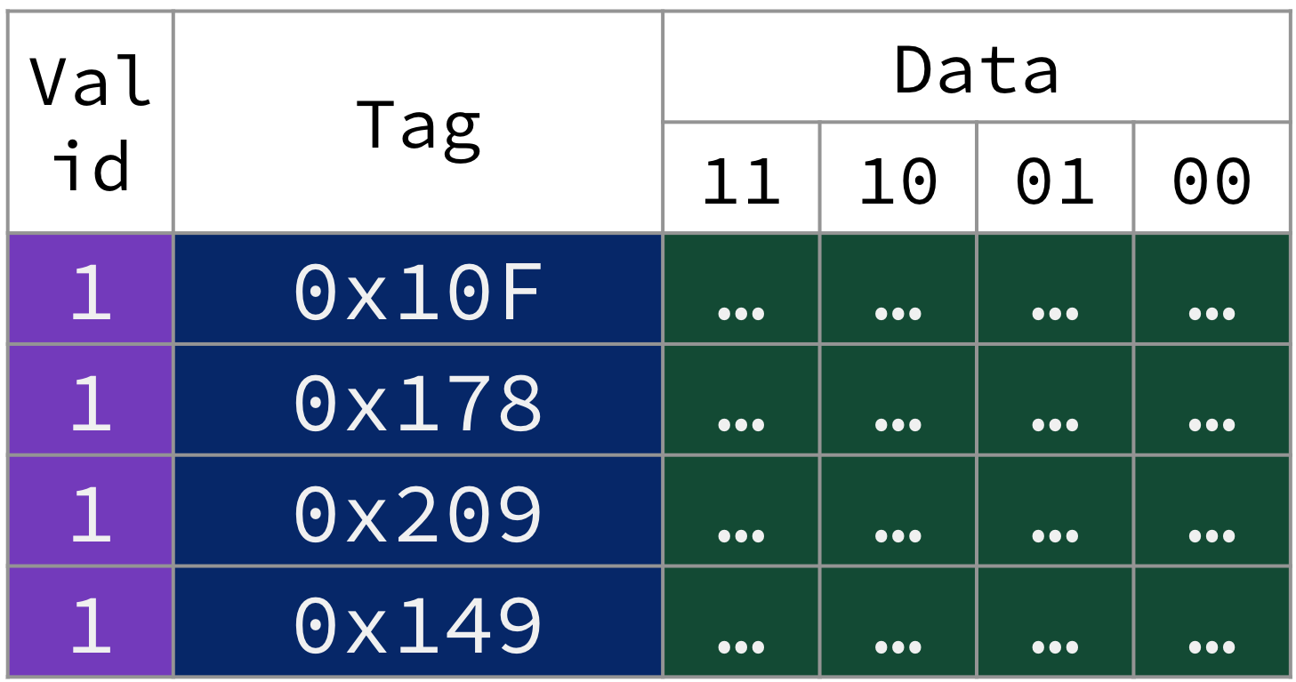
Figure 5:After the five memory accesses described above, our small fully associative cache is full.
A replacement policy defines how the cache controller determines which block is replaced on a cache miss. For fully associative caches, there are several options for replacement policies.
A natural replacement policy is called least recently used, or LRU for short. From Computer Organization: A Quantitative Approach Appendix B.1:
To reduce the chance of throwing out information that will be needed soon, access to blocks are recorded. Relying on the past to predict the future, the block replaced is the one that has been unused for the longest time. LRU relies on a corollary of locality: If recently used blocks are likely to be used again, then a good candidate for disposal is the least recently used block.
Solution: Possible LRU implementation
Answer: Block with tag 0x10F.
One approach is to stare at the memory accesses until you figure it out. Another possible algorithm is to assign a number to each block that tracks access history. On each memory access, reset the number to zero if the tag is valid and matches (or after a cache miss, the updated tag matches), and increment the number if the tag is valid but not matched.The entry with the highest such number[3] is the least recently used.
Load byte @
0x43F. Tag0x10Fis 0.Load byte @
0x5E2. Tag0x10Fis 1,0x178is 0.Load word @
0x824. Tag0x10Fis 2,0x178is 1,0x209is 0.Load byte @
0x5E0. Tag0x10Fis 3,0x178is 0,0x209is 1.Load byte @
0x524. Tag0x10Fis 4,0x178is 1,0x209is 2,0x149is 0.
The tag with the highest number is 0x10F.
Figure 6:Fully associative cache with least recently used (LRU) replacement policy.
6. Load byte @ 0x972. Cache miss.
0x972. Cache miss.Address 0x972 in binary: 0b1001 0111 0010
Tag:
0b100101110010, or0x25COffset:
0b10
Cache Miss. No valid tags in the cache match
0x25C.Access lower level of memory hierarchy. Select the least recently used entry (tag
0x10F). Replace its block with a block’s worth of data from memory starting @ address0x970(0b10001 0111 0000). Write the tag0x25C. Mark valid bit.Read. Read byte in cache block at offset
0b10and return to processor.
Common replacement policies:[4]
Least recently used (LRU): Select the least recently used block for replacement.
Random: Select a block randomly for replacement.
First in, first out (FIFO): Select the oldest block for replacement (even if the oldest block has been most recently used). A queue (using terminology from Data Structures).
While the implementation of replacement policies is out of the scope of this course, we note the following:
LRU incurs a significant hardware cost because the cache must track access history.
FIFO is a reasonable approximation to LRU without adding too much excess hardware.[5]
Random replacement spreads replacement uniformly across the cache, so this policy works surprisingly fine when a workload has low temporal locality.
Table 1:Comparison of cache replacement policies.
| Feature | LRU | FIFO | Random |
|---|---|---|---|
| Description | Replace the entry that has not been used for the longest time | Replace the oldest block in the set (queue) | Replace a random block |
| Implementation | Bit counters for each cache block; see quick check | FIFO queue or similar approximation | Flip a figurative hardware coin |
| Advantage | Temporal locality | Reasonable approximation to LRU | Easy to implement |
| Disadvantage | Complicated hardware to keep track of access history | – | Terrible if workload leverages high temporal locality |
6Write Policy
So far, we have only focused on memory reads with load instructions. But what about store instructions, which write to data in memory?
Recall that cache blocks are copies of data in lower levels:
With a cache, we need to ensure that our main memory will (eventually) be in sync with our cache if we modify data. There are two basic options when writing to the cache:
Write-through: The information is written to both the block in the cache and to the corresponding location in the lower-level main memory.
Write-back: The information is written only to the cache block. The modified cache block is written to the lower-level main memory only when it is replaced.
To implement write-back, we note further that we can only need to write back modified blocks to main memory on replacement. This reduces the miss penalty. To reduce the frequency of writing back blocks on replacement, use a dirty bit for each cache entry.
If the dirty bit is set (
1), the block has been modified while in the cache. When this block is replaced, on a miss, write back this block to main memory.If the dirty bit is not set (
0), the block has not been modified (“clean”). When this block is replaced on a miss, no write-back is needed, since information identical to the cache is found in the lower-level main memory.
Figure 7 animates our fully associative cache with a write-back policy, using the dirty bit
Figure 7:Write back, with dirty bit animation.
7. Store byte @ 0x524. Cache hit.
0x524. Cache hit.Address 0x524 in binary: 0b0101 0010 0100
Tag:
0b0101001001, or0x149Offset:
0b00
Cache Hit. The requested tag
0x149matches a valid cache tag.Write. Write byte in cache block at offset
0b00. Set dirty bit.
In this write-back cache, this memory access does not incur a block replacement (because it was a cache hit). There is therefore no write to memory.
Table 2:Comparison of cache write policies.
| Feature | Write-through | Write-back |
|---|---|---|
| Description | Write to the cache and memory at the same time | Write to the cache. Only write back to memory when the block is replaced. |
| Implementation | Easy | More complicated |
| “Synchronized” with memory?[6] | Yes | No. Sometimes cache will have the most current copy of data. |
| Optimization | – | Include a dirty bit to only write back modified blocks. |
| Hit time for writes | Each write to a cache block also requires a write to memory. Longer. | Multiple writes within a cache block require only one write to memory (the latter happens only on replacement). Faster. |
| Miss penalty | “Read” misses are fast and never result in a write to memory. Shorter. | A “read” miss has variable time, since a write to memory may also be needed if the block to be replaced is dirty. Longer on average. |
| AMAT | Longer | Shorter |
Which write policy should we use? It depends on the level of memory hierarchy. We discuss this more later with virtual memory.
Final note: Fortunately, most cache accesses are reads, not writes. reads dominate cache accesses (all instruction accesses are reads; furthermore, most instructions write to registers, not memory). A block can be read from the cache at the same time that the tag is read and compared. Unfortunately, for writes, modifying a block cannot begin until the tag is checked to see if the address is a hit. Nevertheless, processors do not have to wait for writes to complete and can begin executing other instructions during this time (consider the MEM stage of our five-stage pipeline).
7Walkthrough Summary
In this section, we traced through a cache design for a 12-bit address space with the following features:
Block size: 4B
Capacity: 16B
Placement policy: Fully associative
Replacement policy: Least Reecntly Used
Write policy: Write-back
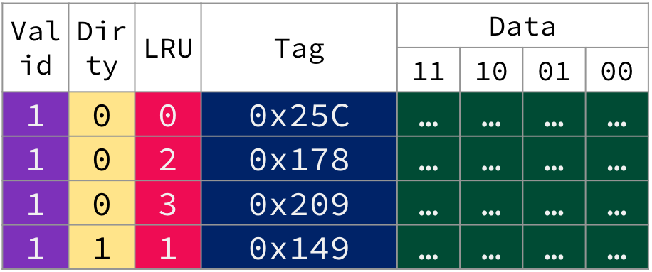
Figure 8:Design of the fully associative cache described in this section’s example.
Cache “metadata”:
Tag: 10 bits
Valid bit
LRU hardware (e.g., a counter)
Dirty bit (to optimize write-back)
7.1Block size and performance
In our tiny cache with 4B-sized blocks, reading a word is equivalent to reading the entire block, but in practice blocks are composed of multiple words (e.g., 16 or 32 words per block).
From P&H 5.3: "The use of a bigger block takes advantage of spatial locality: it decreases the miss rate and improves the efficiency of cache hardware by reducing the amount of tag storage releative to the amount of data storage in the cache. Although a larger block size decreases the miss rate, it could also increase the miss penalty. If the miss penalty increases linearly with block size, larger blocks can easily lead to lower performance.
8Fully Associative: Hardware and Performance
Fully associative caches employ the most flexible placement policy, which is also the most costly to implement in hardware. From P&H 5.4:
To make the search [of a block in a fully associative cache] practical, it is done in parallel with a comparator associated with each entry. These comparators significantly increase the hardware cost, effectively making fully associative placement practical only for caches with small numbers of blocks.
As shown in Figure 9, the hardware is somewhat straightforward: Obtain the tag from the address (i.e., build a wire bundle for the upper bits), then use one comparator per cache entry to compare the cache entry’s tag to the provided tag. OR these comparator results together to determine a cache hit.
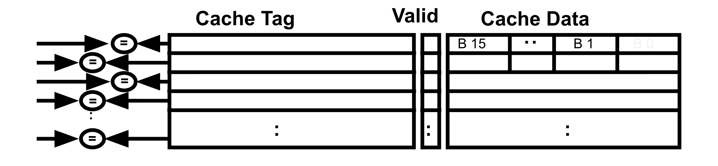
Figure 9:A fully associative placement increases hardware cost.
Fully associative caches are not common in modern processors. Because of the additional hardware needed, higher associativity increases not only hardware but also power.[7] We will see placement policies with lower associativity in the next section that reduce the number of comparators needed and reduce the complexity of each comparator by reducing the width of the cache tag.
Here, “block frame” means the cache entry itself, “block” is the data unit, and “block address” is something that indicates the memory address of the least significant byte of this block. We will more formally define “block address” in the next section.
From Computer Organization: A Quantitative Approach, Appendix B.1: “...add a valid bit to the tag to say whether or not this entry contains a valid address.”
Break ties in some reasonable way, e.g., randomly.
Some of you may be wondering: Why not Most Recently Used (MRU)? Why not last in, first out (LIFO)? While LIFO approximates MRU, both of these policies go entirely against the idea of temporal locality and are consequently a bit silly.
Again, the implementation of a FIFO replacement policy is out of scope. Read Computer Organization: A Quantitative Approach Appendix B.1 for more details.
Also known as data coherency, or cache coherency.
Read more in Computer Organization: A Quantitative Appproach, 5th edition, Section 2.1.